Fusion 360 is a very large, and complicated program, which has CAD (Computer Aided Design) to develop 3D models from scratch or extrapolated from 2D sketches made either within Fusion or imported from other programs, as well as a CAM (Computer Aided Machining) whicl allows you take a 3D model you have made and create commands for a CNC to cut that shape on a CNC. This guide will only cover the latter CAM capabilities.
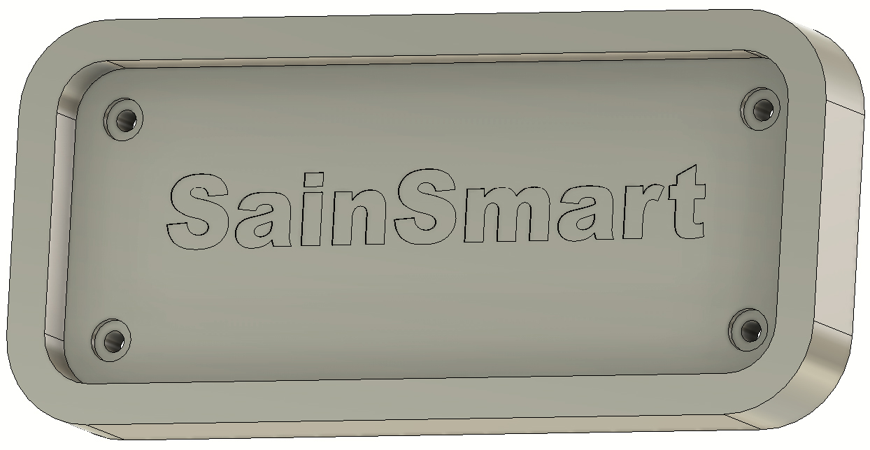
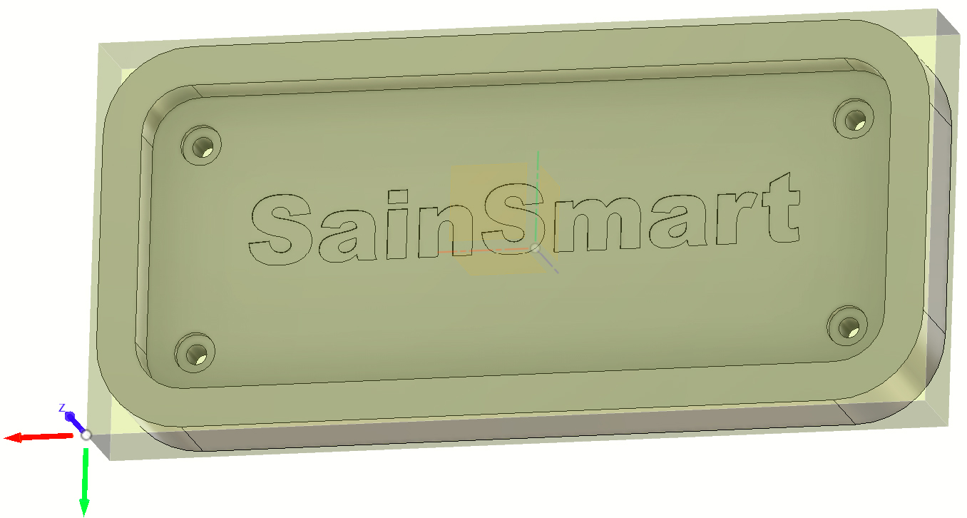
If you are unfamiliar with the CAD portion of Fusion, you will need or at least gain some experience in it, before moving on to the contents of this guide. A good way to do this is to follow along with youtube videos like the ones in this playlist. Not everything in all of those videos will be useful for CNC/CAM Purposes, but you need to know at least enough to make a 3D model, such as the one that will be used through the course of this guide:
If you want to use this model for any reason, it can be downloaded here as a .obj 3D model, though you will need to look up a guide on how to import it.
Step1: Accessing the Fusion 360 CAM/Machining Suite
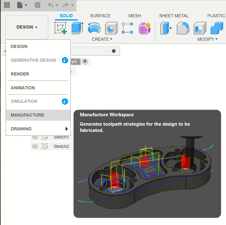
So you have a 3D model, either using the one shown above or one of your own design, and want to get started with the CAM portion of Fusion 360. To start things off and access it, you will need to find this drop-down menu on the top-left portion of Fusion 360.
Once you press the "Design" button, you will see the drop-down menu. From the list, select "Manufacture" to access the CAM package. With this, we can truly begin.
Step 2: Setting Up Your CAM Workspace
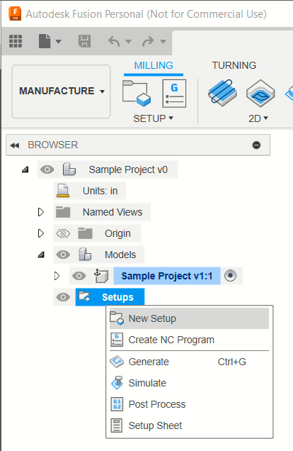
Now that you are inside the CAM/Manufacturing suite, you should see that Fusion 360 looks drastically different from what you are used to. This is normal, it is pretty much an entirely different program hidden within another, but done in such a way as to provide a painless transfer from CAD to CAM.
As a first step to any CAM work with Fusion is to "set up" your workspace. This is a vital step, which can be done a number of different ways depending on your preference, but always take your time and double-check your settings; nothing you do after this step will matter if this step is done incorrectly.
To set up your CNC workspace, you will need to find the "setup" tab from the browser menu, right-click it, and select "New Setup" from the options.
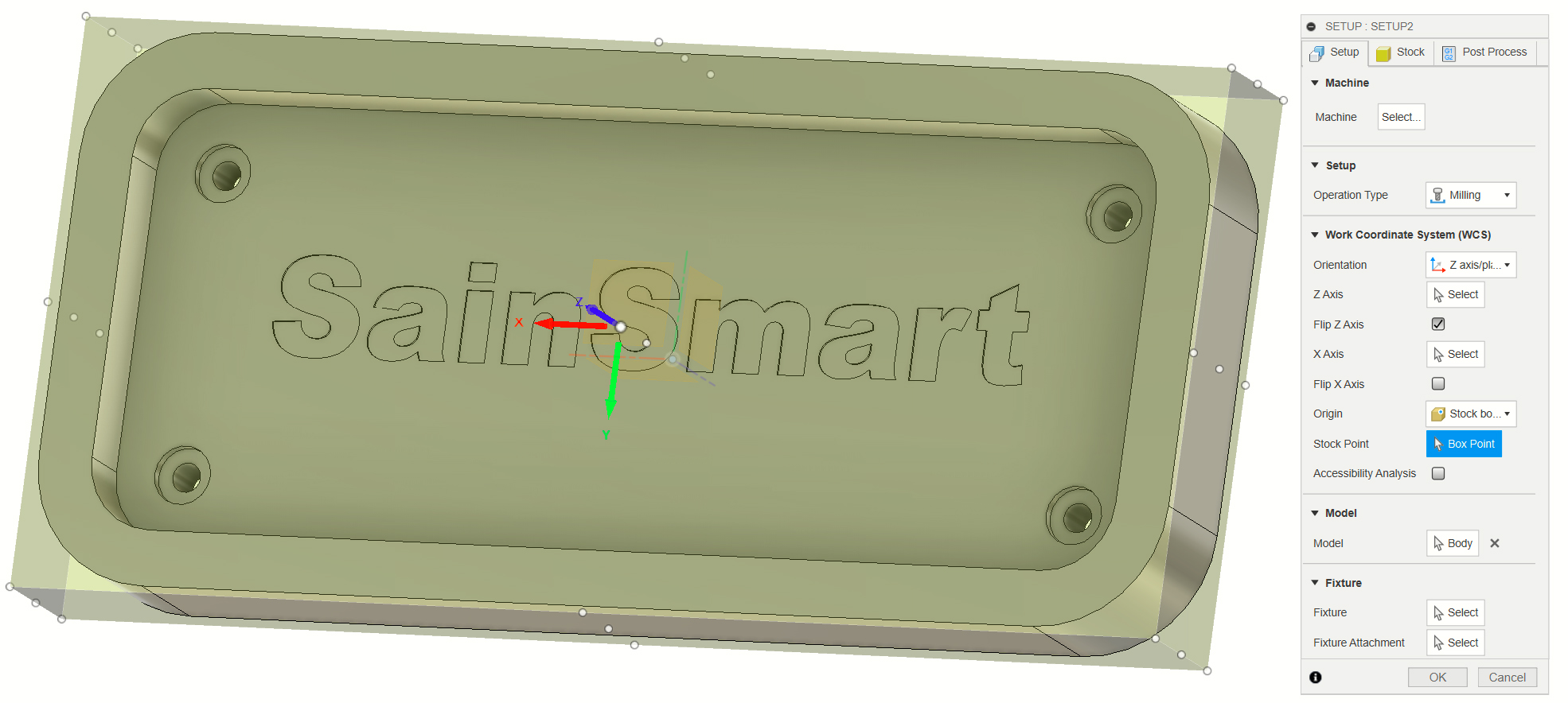
A green box should appear around your 3D model and the Setup Menu should appear:
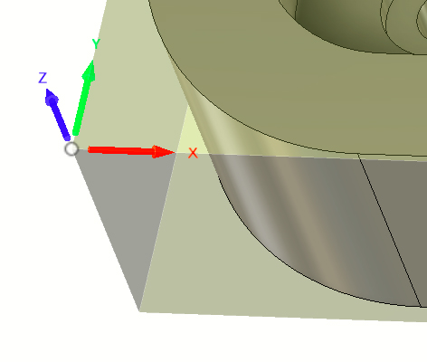
Consider this green box to be your project material, whatever you are planning to cut your project out of, but before we get to that as a part of the "Stock" tab, lets deal with this first "Setup Tab". This whole tab is about figuring out where your Work Coordinate System (WCS) will start from, or the Work Origin, as it is also called. This is the location on your material where you will zero your X, Y and Z axis before running the program. Most commonly, you will want to select the bottom-left corner, or the center for this.
To select your WCS/Work Origin, Make sure that your Origin Drop-down is set to "Stock Box Point" and then press the box point button underneath it. When you do this, you will see a number of white dots show up on your model. These are pre-made points that people most commonly use for this need. For the sake of this project, select the top-most of the 3 points in the bottom-left corner.
Note: No matter where you want your origin to be on the X or Y axis, all projects will want ot use the top of the three white dots in all situations. because you will inevitably need to zero your Z axis on the top of your material. It would be impossible to zero your CNC on the bottom or the center of your materals, after all.
Once you have done so, it should look like this:
Do not worry if the arrows do not look exactly the same, that is the next step. Our goal now is to orient your WCS/Origin so that the CNC knows which way is up, which way is down, which way is left, and which way is right. To do this, we will use those arrows. If click at the tip of any of the 3 arrows, they will rotate as a set. What you want to happen when you are done rotating is for the Z (Blue) arrow to be pointing up and away from the 3D model, and to have the X (Red) and Y (Green) arrows pointing toward your model like this:
With this, the "Setup" tab has been completed, and we can move on to the "Stock" tab. In this step, we will be telling the CAM software as accurately as possible the size of your materials, and the relative position of your 3D model within the materials.
There are a few steps to this:
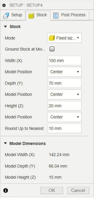
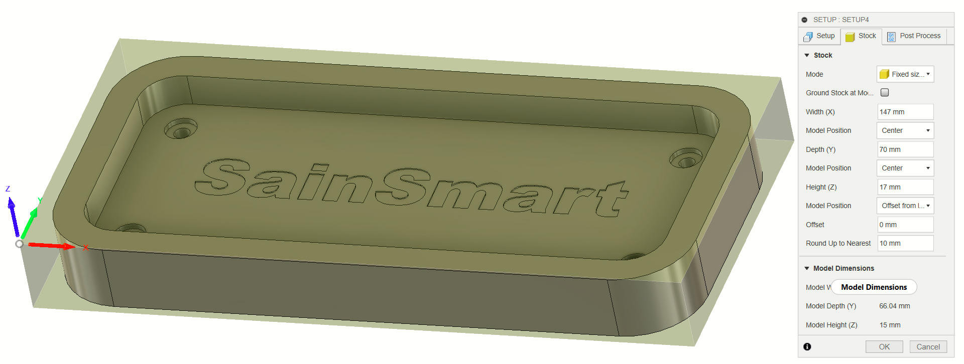
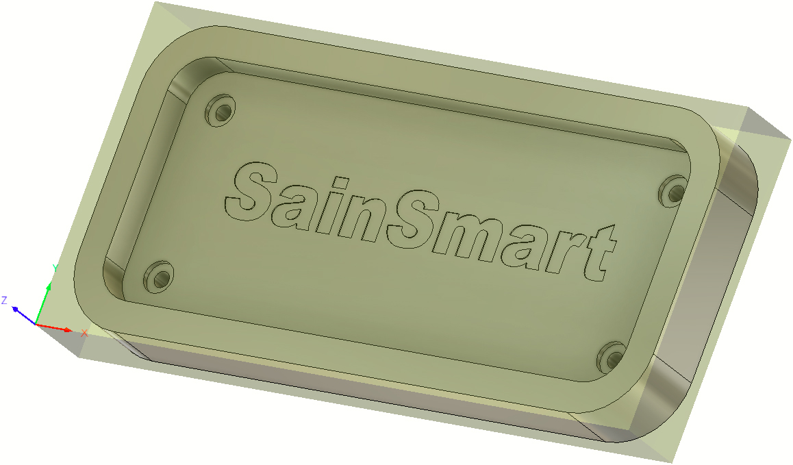
Start by measuring the width (X), depth (Y), and height (Z) of your material and determine if the material suits your model. At a minimum it needs to be at least a little larger than the model itself. For this case, the 3D model measures 142.24mm x 66.04mm x 15mm tall. You can probably get away with a piece of material as small as 143 x 67 x15.5 but that leaves little margin for error during CNC setup, so in this case, lets say our material is 147 x 70 x 17.
Under stock "Mode" set it to "Fixed Sized Box" to allow you to enter the size manually, using the values above.
Below "Height Z" there is a "Model Position" drop-down menu (there is one for each axis, make sure to select it for Z). From that drop-down Menu select "Offset From Bottom". When you do this, a new menu will appear under it called "Offset" set this value to 0. The reason you do this, is so that the CNC knows that the bottom of your material is the same as the bottom of your model, so that everything will cut correctly afterwards.
When you are done, it should look like this:
There is no need to do anything with the "Post Processor" tab, so go ahead and hit Ok to complete the setup process.
Step 3A: Planning your Toolpaths
This is where the hard part starts. I can tell you how to run this project, but not all the processes in step 3 below will directly translate to your own projects, and you will need to learn to select your own endmills and set your own speed and depth values.
This is both an art and a science that we, as a CNC manufacturer are not very equipped to teach you. Learning what endmill to use, in what situation, with what settings, is the larger part of being a CNC expert and it can take a lot of time, practice, and patience to learn.
While we will not be able to teach you most of this, we are happy to try and provide some resources to help you in your learning journey. This video, and this video are a good place to start. Likewise, we also have this buyers guide for our endmills which can tell you what endmill is good for aluminum, or wood, as well as what type of cutting operations they are best at, but it is best to take it with some reservations, as we will never be able to tell the needs of your project as well as you will.
Once you have endmills selected, you will then need to determine feeds and speeds, what we call the settings you program into your CNC for your project. A lot of this will need to come from you as you gain knowledge and experience, but there are resources that try to do the math for you, called a Cut Calculator.
Step 3B: Endmill selection & Tool Library
The goal when you pick your endmills can vary, but as a general rule I think it is best to consider how to cut out your project with the minimal amount of endmills being used. For this project, a 3.175mm flat nose spiral endmill will be used for everything but the SainSmart text, which will be engraved with a 30 degree engraving bit.
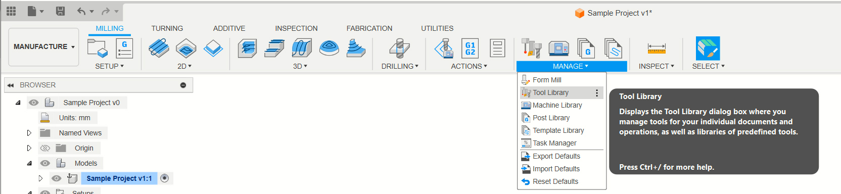
Now that the endmills have been selected, we need to add them to the tool library. To do so, select Manage, and then Tool Library
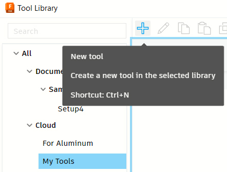
From the options, select My tools (that way you can use these bits in future projects too) and add a new tool by hitting the "+" button:
Once you select "New Tool" then you will need to select the correct endmill type. You can usually pick the one visually closest for the endmills you are to add. For example, for the 3.175mm flat nose spiral endmill I would select "Flat Endmill" and for the 30 degree engraving bit I would select "Engrave/Chamfer Mill". After one is selcted, this menu pops up:
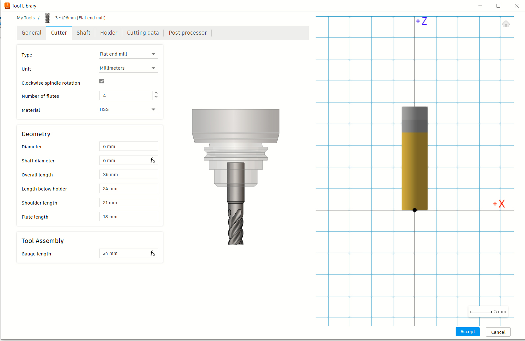
Go to the Cutter Tab, that is the only tab that matters, aside from maybe linking the endmills stores URL for future purposes in the General tab, and all the other tabs (Shaft/Holder/Cutting Details/Post Processor) can be entirely ignored. What really matters it the "Cutter" tab.
Some of you might question why I ignore the cutting data tab as well. You may look at it and see that it could be useful for saving speed and depth of cut settings to a specific endmill, but it is not quite that easy because what material that endmill may be cutting will always be different. You could cut wood one day, metal the next, and plastic after that, and for each case, the settings will need to change. Unless you create a version of the endmill for each material so that you have a specific version saved for each material it would cut.
Instead, we will set these values in the toolpath further along in the guide.
Where you will get these values for the "Cutter" tab will vary if you buy endmills from other vendors, but for our own products, it is on the store page for those endmills. Each page has two different pieces of information, but almost every data point needed on this tab is on the store page for our endmills.
With this data, and using the name of the endmill we have everything we need to fill it out except for one: "Length Below Holder" which is basically fusion asking you how deeply you will install the endmill in the spindle, and how long will the endmill be from the collet to the tip of the endmill.
For the engraving to work this value has to be at least slightly longer than the cutting edge length (The spiral should never go into the collet holder) but should be as close to that as possible, as the less the endmill sticks out, the more rigid your endmill will be while it is cutting.
So how do you get the value? The answer is to consider your material thickness. If I was cutting 20mm deep, for example, then at least 21mm of the endmill would need to stick out beyond the collet, and I would need to measure and make sure this held true after installation. In this case, since our material is only 17mm thick, I will assign the "Length Below Holder" to be 18 and install it into the spindle as such when the time comes.
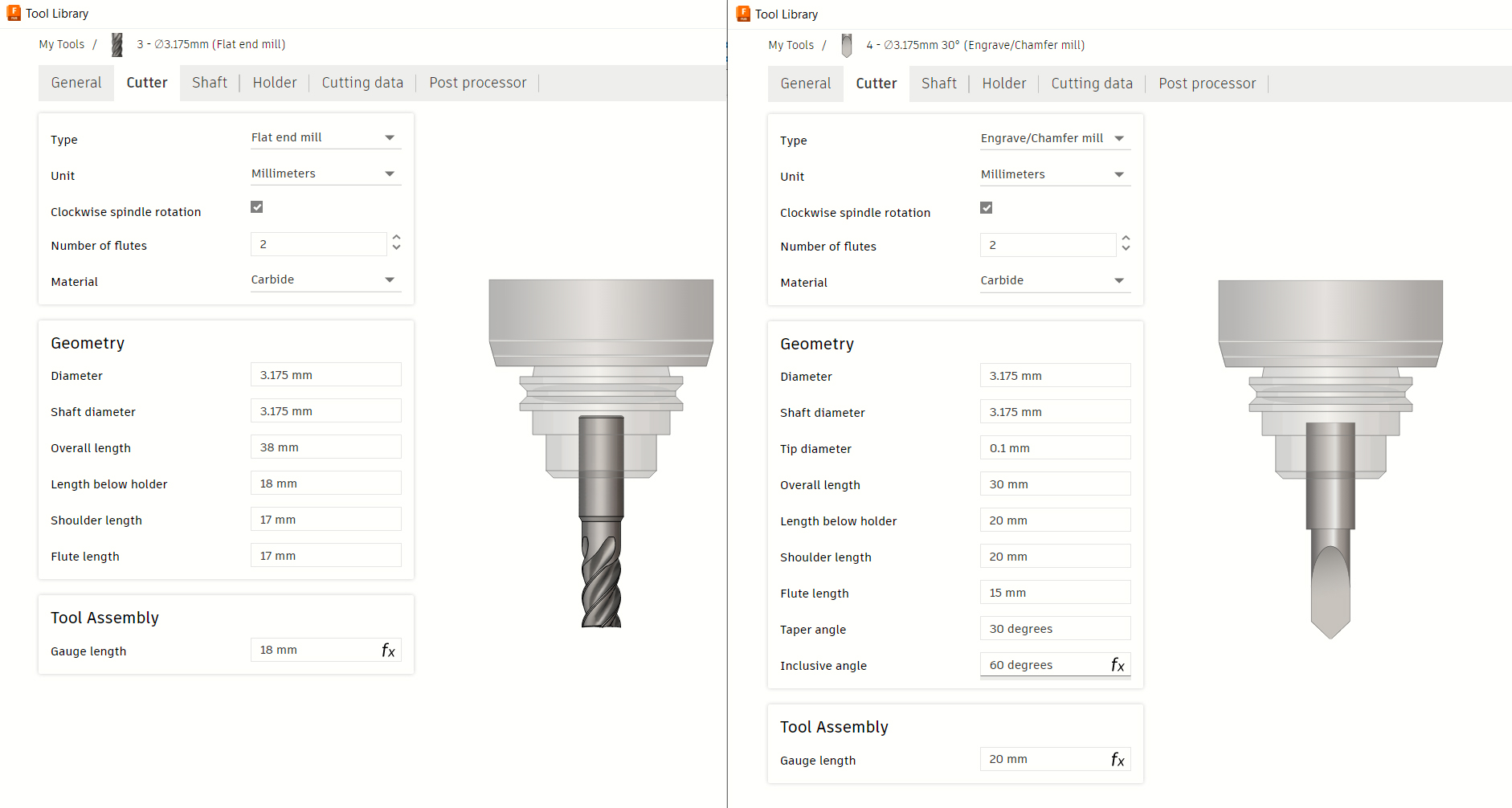
By the time I am done, the settings for both endmills should look like this:
Step 3C: Identifying Toolpaths Needed & Planning the Order of Operations
So we have endmills, now we need to break down what this project needs so that by the time you are done, the cut project looks like what you modeled. So how do you do this?
To be honest, there is not an easy answer. The software will not tell you what you need to do, but there is no way around customers needing to familiarize with all of the different CNC operations, but as a general rule you want to start at the top and work your way down.
Because of this, the first toolpath we need to create is a Face Operation. The purpose of this is to thin away the the material (which is 17mm in thickness) until it is 15mm thick, which is the thickness of our project at its tallest point. Next we would want to do a 2D Adaptive Pocket Operation, to hollow out the inner portion of the project to the second highest point, and we will have them do the 4 circular pockets as well. Next we will do a Drilling Operation to drill all the way through the material, and after that we will do a 2D Contour Operation to cut out the project from the rest of your stock material, but leaving tabs so it does not move around. Finally we will do a Parallel Operation to engrave the "Sainsmart Text" after changing out the endmill.
At the end of all these processes, which will be divided into 2 files exported from Fusion (one for each endmill used) and will be ready to run the files in Candle or UGS.
Step 3D: Face Operation
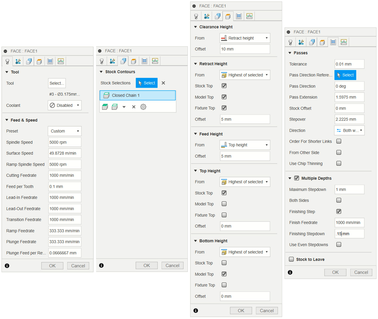
When you select a face operation, a menu will pop up with multiple tabs. It can be very overwhelming at first, but yo do not need to set everything. In this case, as shown above in the images, we will only be dealing with the Tool, Geometry, Heights, and Passes tabs.
Tool Tab
The tool tab is going to be where the most work needs to be done in most cases. you will need to select which endmill you are using and then after you have selected your end mill, you will need to alter all of the feeds and speeds settings based on a variety of factors. There are a lot of features you can modify, enable or disable but for the sake of this guide we will focus on the essentials:
Spindle Speed & Ramp Spindle Speed: For the sake of simplicity, make a habit of setting both of these settings equal to one another. The maximum RPM of most of our stock CNCs is usually 10000, so you can set any value between 0 and 10000.
Cutting Feedrate: This is the primary value used to dictate how fast your CNC tries to slice through your project. This value varies wildly depending on how deep you are cutting per pass. The deeper you cut, the slower you have to set this.
Lead-In/Lead Out/Ramp/Plunge Feedrate: These settings dictate cutting feedrate through various more stressful movements your machine might make. These should always be lower than your cutting feedrate. Generally for Lead-In/Lead-Out, 15-30% slower than the cutting feedrate is a good setting to test at, and 30-50% slower than the cutting feedrate for Plunge/Ramp feedrate.
The other values in these tabs will either adjust automatically, or do not need to be adjusted unless you want to get into more advanced controls. To see what anything else does, you can over your mouse over the option and Fusion will briefly explain what the setting does.
Geometry Tab
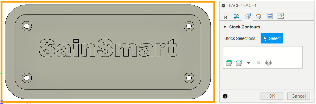
For most operations, this tab is about telling your CNC what is included in the toolpath. This will be more important in all of the other toolpaths, but for the case of this surface operation, you do not select anything, as the default selection is to use the entire workspace you made in step 2. For a surfacing operation, though, getting the whole area is just perfect.
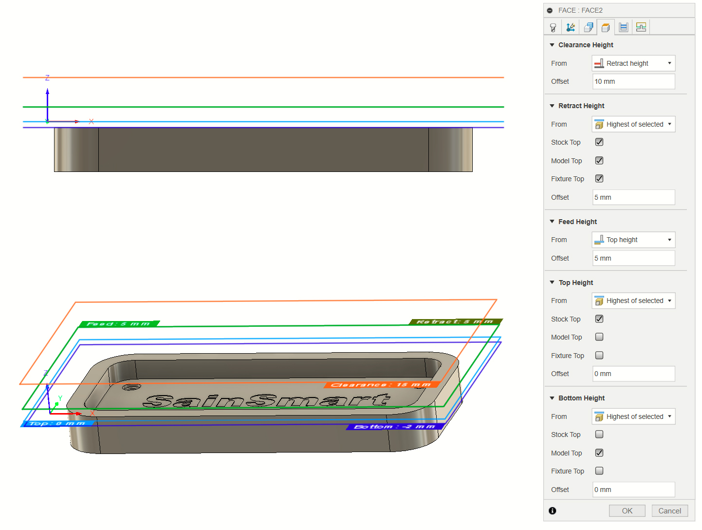
Heights Tab
The heights tab has a visual interface that is a little hard to display in a 2D image, but what this tab deals with is creating Z axis limitations and establishing reference points that the software will use when generating Gcode. For anyone with a larger CNC, anything larger than our 3018s or the 3020 CNC for the most part, you do not need to edit this ever. For those smaller machines, if you do not modify your Clearance, Feed, and Retract heights to be lower, you may find that your Z axis will retract right into your Z limit switch, causing the project to abort.
Larger CNCs with higher Z travel space do not have this issue though, and this tab can be left alone.
Passes Tab
There are a few settings to work with here, but they are all very important to the success of your engraving:
Stepover: This value is almost always very high by default. As a rule, stepover should never be more than the full diameter of your endmill (if it is pointed, then the diameter of the point at its narrowest), but I rarely suggest going that height a value. I usually suggest:
3/4 Endmill Diameter: This is for rough cuts, where the quality of the surface leftover is not important, or will be cut further
1/2 Endmill Diameter: I use this for a balance between quality and speed. The surface leftover is not going to be amazing, but it should be easy enough to sand afterwards.
1/4 Endmill Diameter: This value or less (depending on your patience, since the CNC will take longer the lower this value is) is what I use for a good looking finished surface.
Multiple Depths: This is usually disabled by default, but you almost always want this enabled aside from fine engraving work. If you do not do this, then the CNC will try to cut to the full depth in one go. Even for our larger CNCs this is not something that is generally desirable. Once enabled, you will need to go through the settings therein:
Maximum Stepdown: This will be the value where you set how deep you want the CNC to cut per pass. There is no one right answer for this, and what the CNC can handle will vary greatly based on the feeds and speeds you set in the first tab. If you cut faster you generally need to cut shallower, or you can cut slow and deep. If you ever make a program and it comes out looking less than good, this is one of the first values you should adjust lower to see if your project cuts better next.
Finishing Step/Finishing Feedrate/Finishing Stepdown: This is a great little feature that you will not always need, but by enabling it, you can instruct the CNC to cut slower and shallower for the final pass. It is a great feature that I use often that prevents me from having to do the same in an extra toolpath.
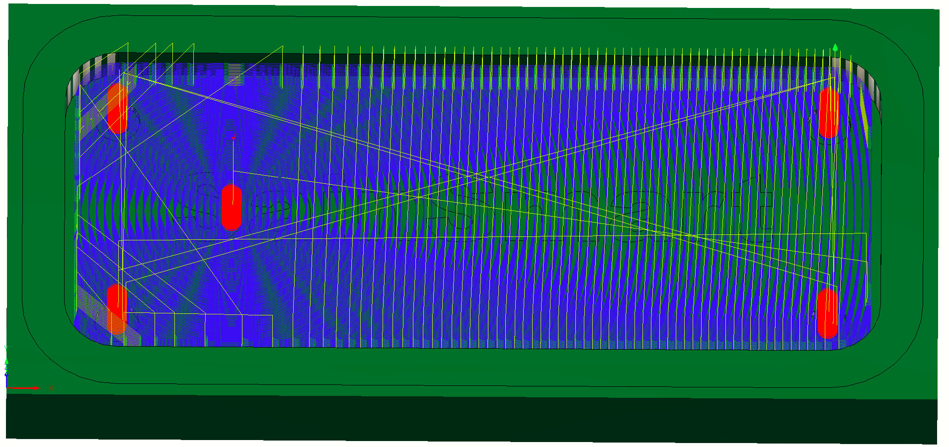
After this tab, you can be done with your surfacing operation and hit "Ok" after which the software will generate the toolpath. This can take some time depending on how powerful your computer is, but it would look something like this at the end:
You can even simulate how this will cut by selecting "Simulate With Machine" in the Utilities tab and hitting play.
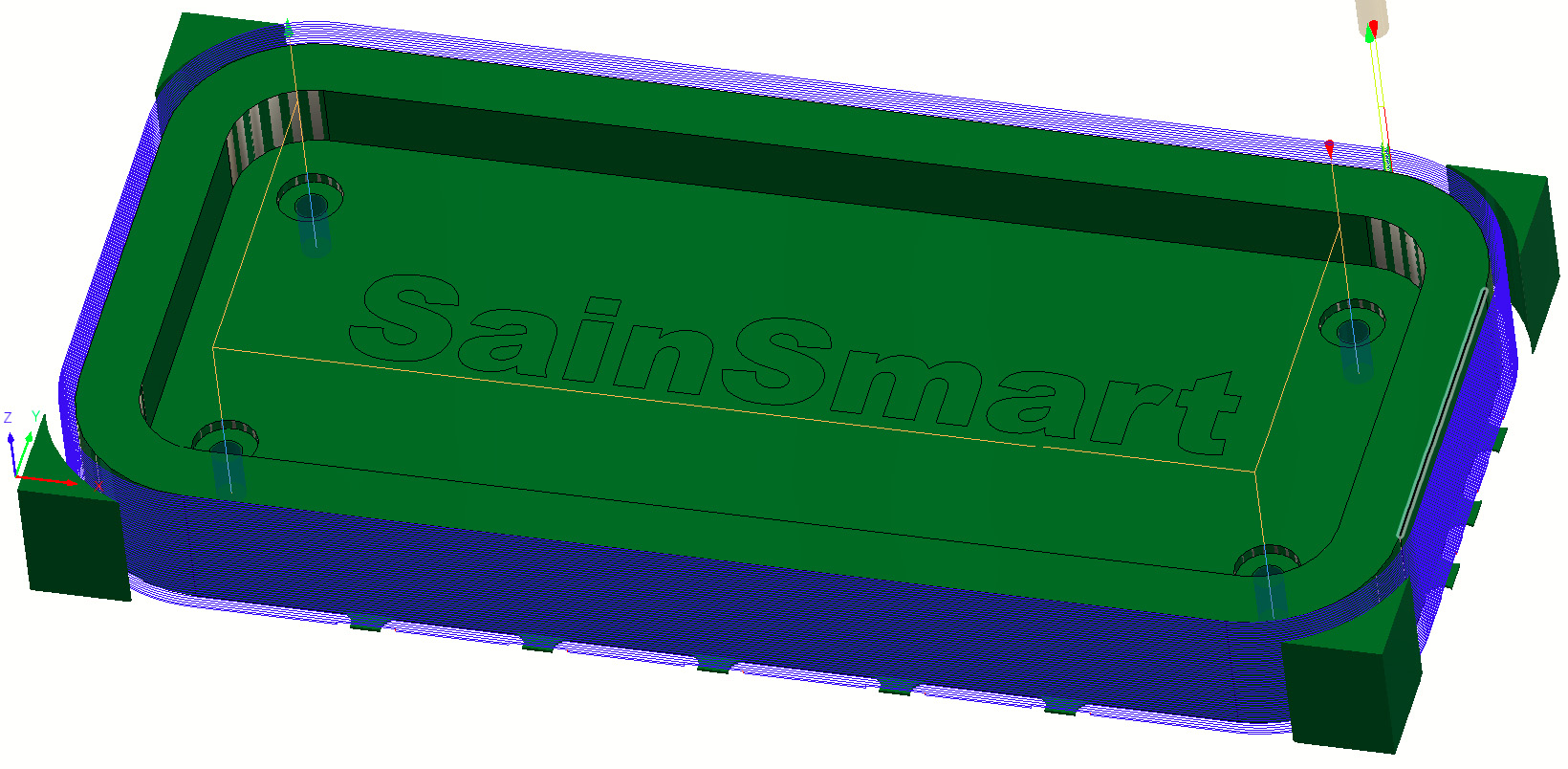
Step 3E: 2D Adaptive Pocket Operation
For this toolpath, we are going to dig out the center of the tray, as well 4 recessed holes. Once you select it you will find that the menu is extremely similar to that of the Face operation. You will need to select your endmill and set your feeds and speeds as you did before in the Tools tab, and then go over to the Geometry tab:
Geometry Tab
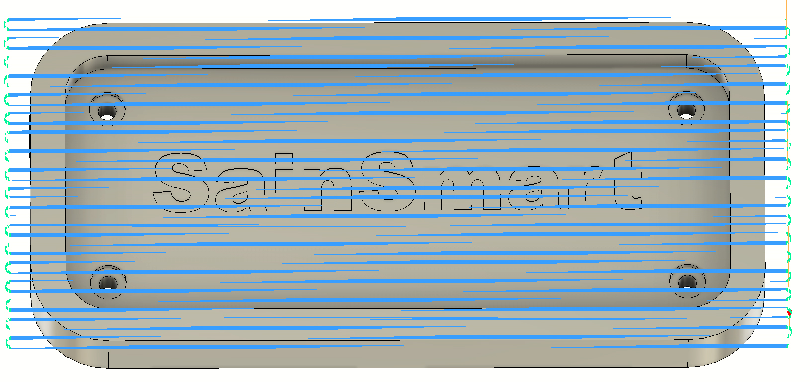
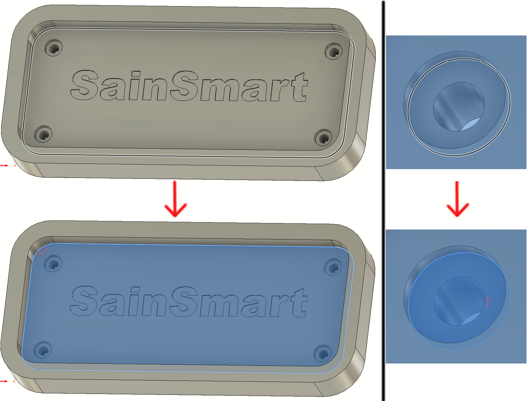
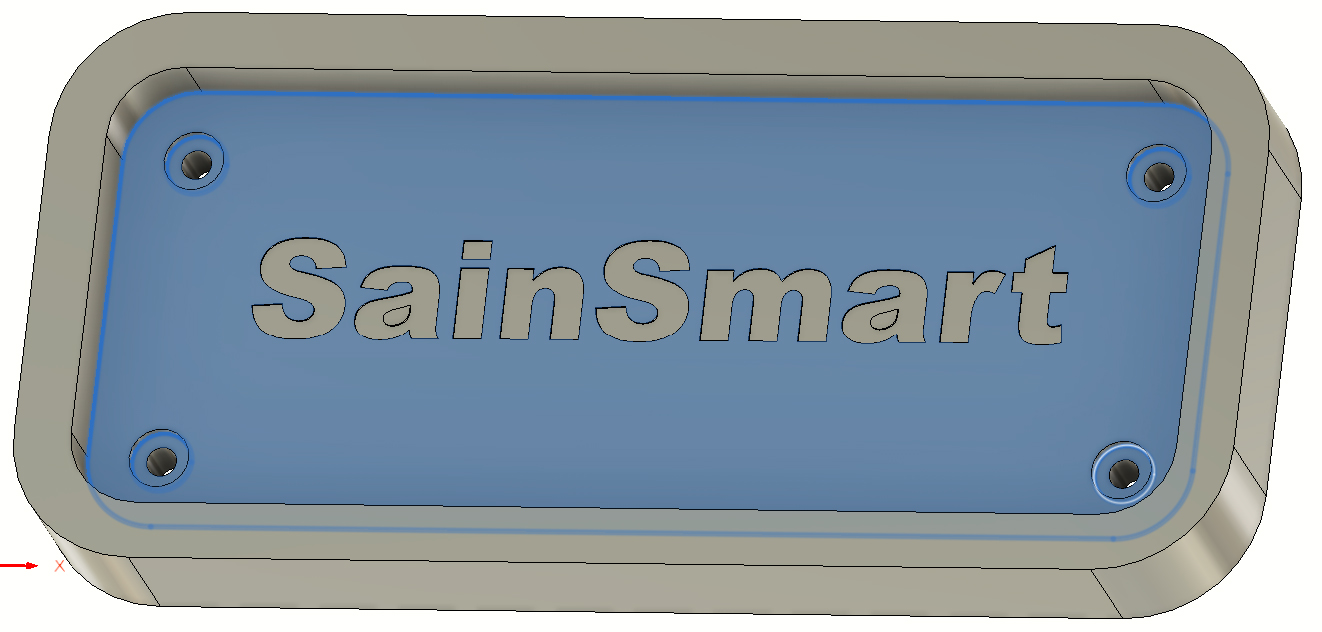
In this tab, we will be telling the CNC where we want it to cut, because unlike with the face operation, it would be detrimental to cut everything. To this you can select parts of your model, namely surfaces and edges. For the process below, select only edges, you can tell based off of what is highlighted while your mouse hovers over it. Start by selecting the lower edge of the pocket larger pocket, and then select the lower edge of each of the 4 smaller round pockets. Here is a before and after about what each pocket should look like before you click it, and after:
If you selected a surface, instead of the corner (the wrong way) you would see that the "Sainsmart" Text is not highlighted. Here is what it would look like if you did it incorrectly:
It would not come out at all if you did it this way, so make sure you select the edges, and not the surfaces.
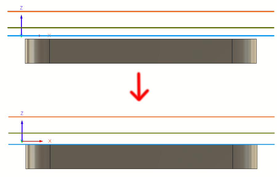
Heights Tab
This is pretty much the same as with the Face operation, but there is one exception. If you flatten out the display, you will see the Blue "Top" tab is not touching the surface of your project. It is still hovering at the height before the Face operation. Realistically you can leave it like this, it would just cut needlessly in the air a bit, but if you want to be efficient, you will want to lower this tab to the -2 position (or until it visually looks flat to your surface, like below, so that it doesn't try to cut into the air at all.
Passes Tab
This one is going to look a little different, as this is a more advanced toolpath that cuts more efficiently. Your main concern should be the "Multiple Depths" option which should be enabled and set like before, but if you wanted to adjust "Optimal Load" You can treat that like the "Stepover" when you did the Face operation, so if you lower this value it can cut less to put less stress on your CNC/endmill. Generally the default value is good, though.
With that, you should be good to go and hit ok. Do not worry if this one takes a little while to generate, it is worth it to create a more efficient toolpath:
Step 3F: Drilling Operation
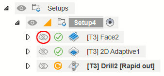
This one is a bit easier, all we want to do is drill away the holes that go all the way through your project. You might notice that things are getting a little busy on your model with all the toolpaths piling up. If you click the eyeball next to each prior operation as shown in the red circle below, you can hide them from view:
With that out of the way, so you have a clear view, select the Drill operation from the top Menu. The Tool Tab you can do as normal for what values apply, since you will be using the same endmill, but it is advisable to slow this one down. Endmills are not as good as a drill bit when it comes to drilling, so if you are too aggressive it will widen the holes too much or clog up the endmill.
This time around, for Geometry you will want to select the 4 holes like so:
Next go to the heights tab and lower the Clearance and Retract heights if needed, and then focus on the Cycle Tab (looks like the Passes Tab, which is the most important for this operation.
Cycle
Because we will be drilling fairly deep, and because we want to make sure the hole is cleanly cut and as close to the width of the endmill as possible, you will want to select "Deep Drilling - Full Retract" from the Cycle type. This causes the endmill to retract fully out of the hole it is cutting after each peck, allowing the endmill to cool for a moment and fully clear any debris to keep the endmill from clogging with material.
Pecking Depth: You will want to lower it from the default value. This tells the software how deep you want the endmill to cut per peck. I usually suggest 1/4 the diameter of the endmill for this, if not less.
Pecking Depth Reduction: I do not usually use this, as even very conservative settings for drilling tend to be fairly quick, but if you wanted to try and make it cut faster, you could set this value to reduce the pecking depth by that amount per peck. This would in theory allow you to use a much more aggressive starting Pecking Depth, and then have it be very shallow as it gets deeper and deeper.
Dwell Before Retract/ Dwelling Period: This is not mandatory to enable, but it cuts cleaner if you dwell for .25 or .5 seconds. Valuable if you really need the width of the drilled hole to be as exact as possible.
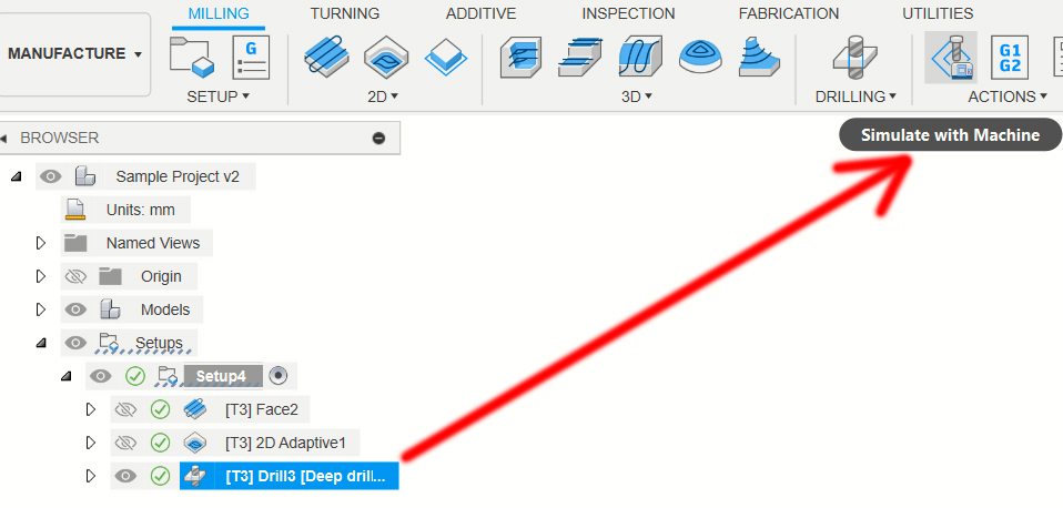
With that done, your Drilling toolpath is good to go, hit ok. If you want to simulate just the drilling operation you can, by selecting only the drilling operation (Make sure the Eye is open) and then pressing the simulate button like this:
You can even select multiple simulations together by holding the CTRL key before clicking each operation and then selecting simulate.
Step 3G: Contour Operation
This will be the last operation with the 3.175mm endmill, and with this we will be cutting out the project from the rest of your stock material. You might wonder why you would want to do this before engraving the Sainsmart text first, but the reason for this is that we will be using tabs to hold the project in place even after being cut.
Start off by setting up your Tool Tab, and then go to Geometry. You will want to select the bottom line of your material like so and then enable tabs as well:
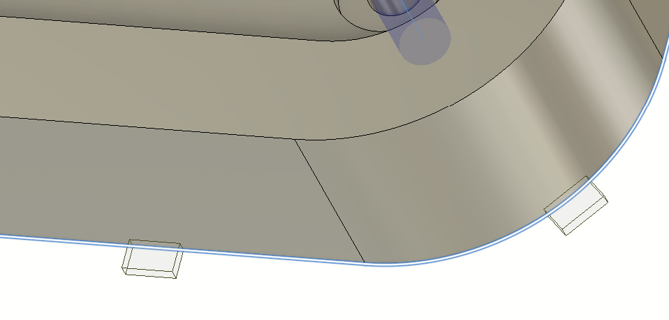
Once you enable Tabs, you will see a number of red boxes show up like those shown in the image above. In these spots the CNC will not cut all the way through, creating these tabs that you can later cut out by hand, or just breaking them off and sanding the surface to remove a mark. Here are some settings to look out for:
Tab Shape: You can select Rectangle or Triangle, but I suggest keeping it as a rectangle
Tab Width\Height: These settings are a balancing act. The narrower, and shallower your tabs are, the easier they will be to break off afterwards and the easier it will be to clean up any marks, but if you make them too narrow/shallow then it could break while engraving.
Positioning Method: As you can see in the image above, there are tabs on the curved corner, which is less than ideal. To prevent this, you can set the Positioning Method to "Segment" and then the curves will not get tabs.
Tab Distance: You can use this value to set how many tabs you want. The larger the value, the less tabs there are. This, too, is a balancing act between having too many and too little.
Manual Tabs: As the name implies, you can set the tabs manually this way by clicking where you want them.
With those set, you can move on to the Passes Tab, where the only think you have to do is enable multiple depths and set it accordingly. Once you are done it should look similar to this:
Step 3H: Tool Change & Engraving Operation
Last, but far from least, we have the Engraving of the Sainsmart Text using the 30 degree V-bit that we added to the tool library. Under Tools Make sure to select it, because it will default to whatever endmill was used previously. When it comes to setting feeds and speeds, you need to remember that your endmill tip is only .1mm in diameter at its point. That is thin enough that it can and will easily break with settings that are too aggressive.
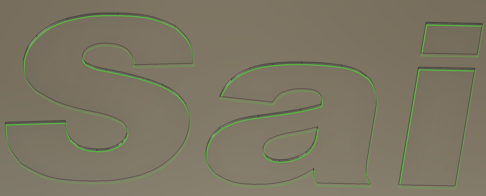
Geometry
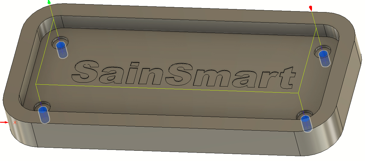
Machining Boundary: There are a few options, but unless you want the engraver to cut most of your project you will want to select "Selection" and then you can select each letter individually. Unlike the other operations so far, you will want to select the lowered surface of each letter, and not the lines. Each letter should look like this when you are done:
Under "Tool Containment" make sure to select "Tool Centered on Boundary" with an offset of .25 mm and then you can go to the Passes Tab. This is the one case where you do not need to enable multiple depths, since the text is only .25mm deep to begin with. What you do need to set is Stepover. It will need to be very, very low. The tip of the engraving bit is just .1mm and remember the suggested values for things like this:
3/4 Endmill Diameter: This is for rough cuts, where the quality of the surface leftover is not important, or will be cut further
1/2 Endmill Diameter: I use this for a balance between quality and speed. The surface leftover is not going to be amazing, but it should be easy enough to sand afterwards.
1/4 Endmill Diameter: This value or less (depending on your patience, since the CNC will take longer the lower this value is) is what I use for a good looking finished surface.
With that being said, I do not suggest a stepover above 1/2 in the case of engraving bits. The tip is just too fragile. usually 1/4 or less of the diameter is best.
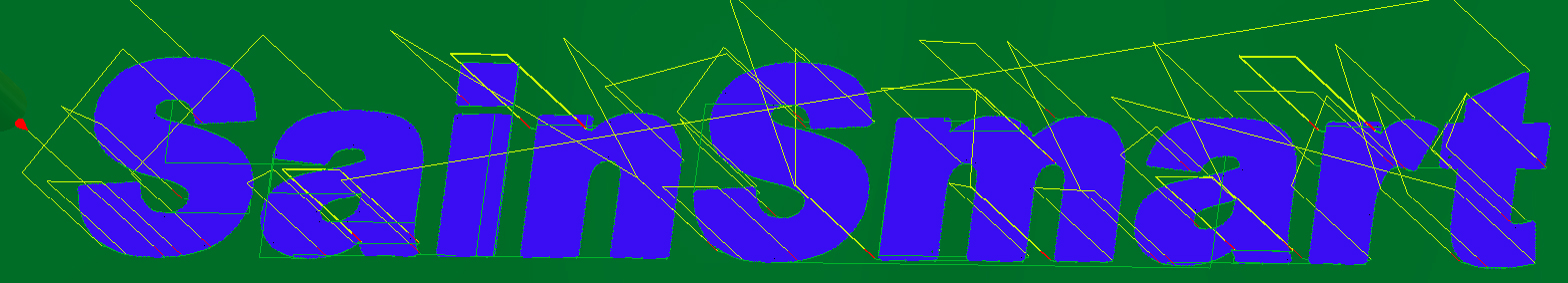
Once you are done, hit ok and let the toolpath generate. It should look something like this:
With this, all the toolpaths are made.
Step 4: Exporting Toolpaths
Now that we have gotten this far, the goal is to export 2 total files. The first file will have all the operations with the 3.175mm flat endmill, and then the second file will be just the engraving toolpath, which uses the 30 degree engraving bit.
Before we get started, it is vitally important that your toolpaths are in the correct order. If you did anything out of order from what was shown here, you will need to drag and drop files on the side menu to make it be in order. When this occurs you will also have to re-generate the toolpaths by right-clicking each item once everything is in order (on the left menu) and select "Generate".
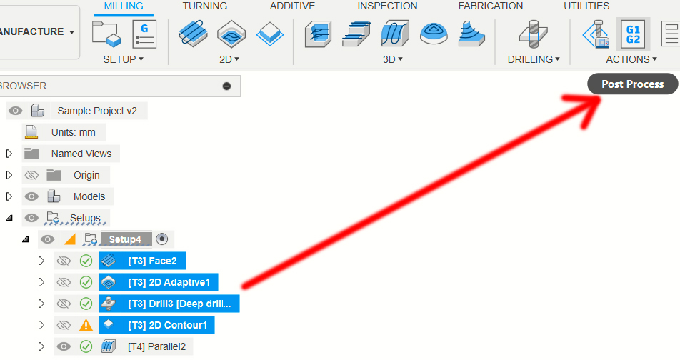
With everything in order, hold the CTRL key and select all but the engraving toolpath. With everything selected, press the Post Process button:
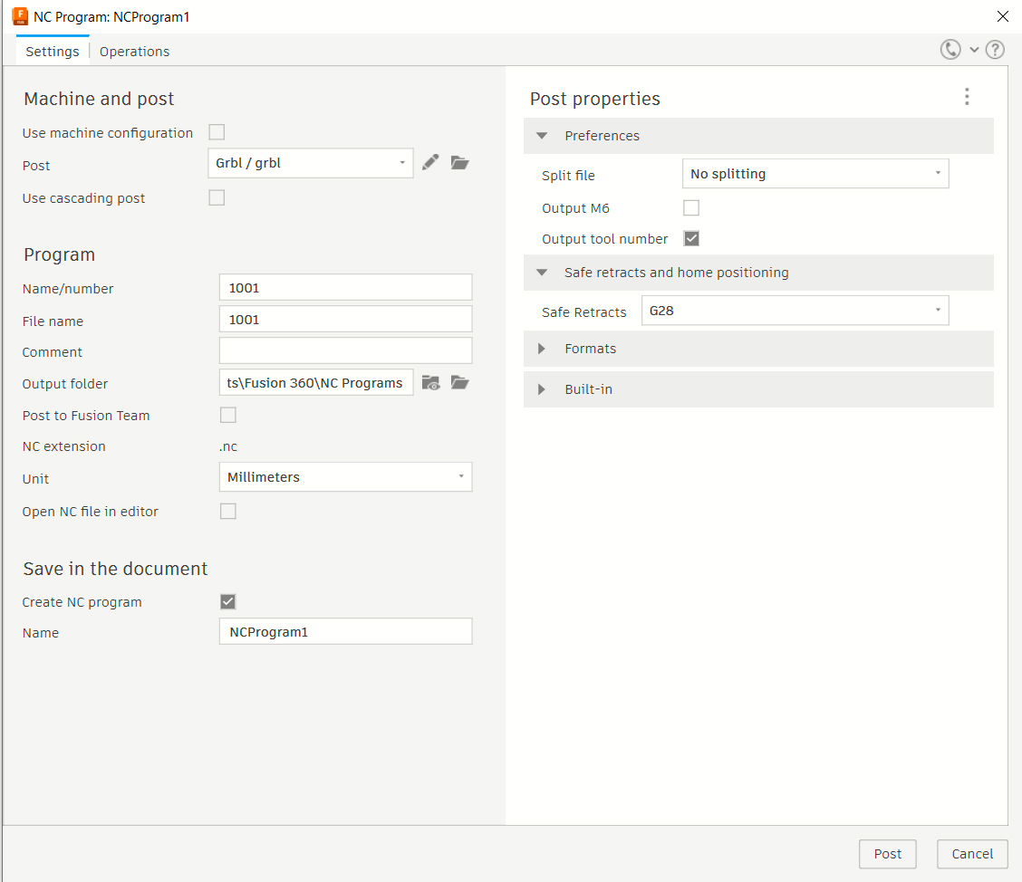
However many of the toolpaths/operations you have selected, all of those will export into one file you can run by itself. Once you have done this, the Post Process menu will come up:
Here you will want to go to the Post setting, select "From Libray" and then under the Fusion Library, search for GRBL. There are a number of posts, like "GRBL Laser", but you want just "GRBL" by itself. Once selected, save it to your local or cloud library, name your file and select where it will save to, and the unit of measurement you used, then hit Post. The file will be saved and exported.
Now select your engraving file and do the same, most of the settings will be saved so you just have to name the file.
Step 5: Running the exported Program
You should now have two named exported text files with a .nc extension. These can be opened and run in a program like Candle or UGS. One thing you will need to do in either Program to make the Fusion files work is to:
1. Home your CNC
2. Jog the Z axis down by 5mm
3. Type G28.1 into the command console and hit enter
You are now good to run your files and you only have to set this the one time. For those unfamiliar with how to run two programs using different endmills for the same project, see this guide for more information on how to do so in Candle.


![[Part 2] Advanced CNC Design with Vectric Aspire](http://www.sainsmartshop.com/cdn/shop/articles/Frame_36747_2_f374d9f8-a0e0-465e-80ed-1bb349fc0a3b.png?v=1737359282 "[Part 2] Advanced CNC Design with Vectric Aspire")